LUOYANG DATANG ENERGY TECH CO.,LTD


PE Gas Pipe Pressure Testing: Strength vs. Tightness
A PE100 SDR11 gas pipe can leave the factory with a perfect hydrostatic test record—no failure at 20°C, 100h, 12.0 MPa hoop stress—and still fail on site. Not because the pipe was defective, but because the thing being tested on site is not the pipe. It is the entire installed system: pipe, fittings, fusion joints, transition connections, and every meter of trench backfill that was supposed to protect them.
That distinction sits at the center of PE gas pipe pressure testing. Buyers and installers routinely conflate two tests that answer two different questions: strength test asks whether the system can survive the pressure without structural failure; tightness test asks whether it leaks. Passing one does not automatically mean passing the other, and treating them as interchangeable is how projects end up with a signed test sheet and a leak six months later.
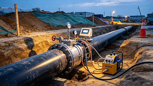
PE gas pipe pressure testing site with pressure gauge and data logger
Strength Test vs. Tightness Test: Two Different Tests
The quickest way to see the difference is to put the two tests side by side. The values below reflect GB/T 51455-2023 and the PE-specific provisions of CJJ 63-2018, which are the governing references for buried PE gas piping in the Chinese market. They are not universal constants—EN 1555 and ASTM D2513 projects operate under different national annexes and project specifications—but the logic of the two-tier test is consistent across standard systems.
| Strength test | Tightness test | |
|---|---|---|
| What it proves | The installed system can withstand the target pressure without rupture, leakage, or visible deformation | The system has no leakage path at operating-level pressure |
| Test pressure (PE, SDR11) | 1.5× design pressure, minimum 0.4 MPa | 1.1× design pressure, minimum 0.1 MPa for medium-pressure and above (some project specs use 1.15×) |
| Hold duration | 1 h at test pressure, then observe for ≥30 min | 24 h continuous, with readings at least once per hour |
| Pass criterion | No pressure drop, no leakage, no visible deformation | Corrected pressure drop < 133 Pa (GB/T 51455-2023, §11.4.5) |
| What it catches | Weak fusion joints, pipe defects, inadequate structural margin | Micro-leaks, seal failures, slow loss paths that strength test can miss |
The 0.4 MPa floor on the strength test is not an arbitrary round number. A PE100 SDR11 pipe has a nominal pressure rating in the range of PN 10–16 depending on the design coefficient and application temperature, and the 0.4 MPa floor exists to ensure that even low-design-pressure systems receive a meaningful structural challenge rather than a test that sits too close to operating pressure to reveal anything. The 133 Pa threshold on the tightness side is similarly deliberate: it is small enough to flag a real leak path, but large enough to absorb the pressure and temperature “noise” that a 24-hour test inevitably accumulates.
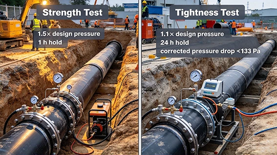
Strength test vs tightness test pressure and hold duration comparison for PE gas pipe
How Corrected Pressure Drop Is Calculated
The tightness test is where most procurement misunderstandings happen, because the pass criterion is not the raw pressure gauge difference. A 24-hour test in a trench is exposed to ambient temperature swings and barometric pressure changes. A gauge that reads 200 Pa lower at hour 24 may not have leaked at all—it may simply have cooled down.
The corrected pressure drop calculation accounts for both:ΔP=(H1+B1)−(H2+B2)×273+t2273+t1
Where H₁, H₂ are gauge readings at start and end, B₁, B₂ are barometric readings, and t₁, t₂ are the gas temperatures inside the pipe at start and end. The temperature correction term is not cosmetic. A 10°C drop in gas temperature over 24 hours can easily produce a raw gauge pressure change of several hundred Pascals in a large-diameter pipe section. Without correcting for it, a perfectly sound system can be failed—or a real leak can be masked by a temperature rise.
This is also why GB/T 51455-2023 requires readings at least once per hour, not just at the two endpoints. A single start-and-end reading cannot distinguish a leak from a temperature transient. The hourly record creates a pressure-time curve, and the shape of that curve tells the story: a steady, near-linear decline suggests a leak; a decline that flattens out as the backfill temperature stabilizes suggests thermal equilibration.
A practical note for buyers reviewing test records: if a supplier or contractor presents a tightness test report with only “start pressure” and “end pressure” and a pass/fail stamp, ask for the hourly log. The hourly log is where the engineering lives. Without it, the report is a conclusion without evidence.
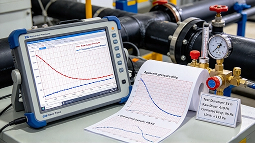
Corrected pressure drop chart for PE gas pipe tightness test with temperature correction
Water or Air? A Safety Decision
PE gas pipe sites often default to compressed air for tightness testing because it avoids the dewatering step and the risk of residual moisture in the line. That is a legitimate operational consideration. It is not the whole picture.
The fundamental physics is unforgiving: water is nearly incompressible; gas is not. A pipe section pressurized with water stores very little compressed energy. If it ruptures, the pressure vents with a relatively small energy release. A pipe section pressurized with air or nitrogen stores the energy used to compress the gas, and a sudden failure releases that stored energy in a blast wave that can project fragments and injure personnel well beyond the immediate trench line. Industry guidance across liquid and gas pipeline testing is consistent on this point: hydrostatic testing with water is the preferred medium wherever the system can tolerate it, precisely because the stored-energy consequence of failure is orders of magnitude lower.
That said, “water is safer” does not mean “water is always practical.” A PE gas line that will carry dry natural gas may have stringent moisture limits, and residual water after hydrostatic testing is a real commissioning problem. CJJ 63-2018 acknowledges this tension directly: tightness testing medium is preferably compressed air, but if the strength test used water, the line must be fully dewatered before tightness testing; if the strength test used air, the pressure should be reduced to the tightness test level in a controlled sequence rather than dumped and re-pressurized. The standard does not declare one medium universally superior. It sets a sequence and a discipline.
Where this lands for a buyer: the medium choice should be written into the test plan, not left to the crew’s habit. If the specification calls for water strength testing followed by air tightness testing, the dewatering and drying procedure needs to be defined before the test, not improvised after it. If the line cannot tolerate water at all, the pneumatic test plan needs a written hazard assessment, exclusion zones, and a pressure ramp rate that is slower than what would be acceptable for hydrostatic testing.
What Factory Testing Does Not Replace
A frequent procurement question: “The pipe already passed a hydrostatic test at the factory. Why do we need a strength test on site?”
Because the two tests sit at different levels of the system hierarchy.
| Factory hydrostatic test | Site strength test | |
|---|---|---|
| Object tested | A pipe specimen or a pressure test assembly | The installed piping system, including fusion joints and fittings |
| What it verifies | Material-level long-term hydrostatic strength | Installation-level structural integrity |
| Typical conditions | 20°C, 100 h, 12.0 MPa hoop stress for PE100 (EN ISO 1167 / ISO 4437 lineage) | 1.5× design pressure, minimum 0.4 MPa, 1 h hold |
| What it cannot catch | A poorly fused joint, a misaligned fitting, or a damaged section introduced during installation |
The factory test tells you the material compound is capable of sustained pressure performance. The site test tells you the system that was actually built in the trench can hold pressure. A PE100 compound with a perfect 12.0 MPa, 100-hour hydrostatic record can still produce a leaking system if the fusion parameters were wrong, the heating tool temperature drifted, or the joint was cooled under mechanical load. That is not a material failure. It is an installation failure—and only a site test is positioned to catch it.
This also connects back to the ISO 4437-1:2026 update. The new edition adds PE 100-RC material grades with enhanced slow-crack-growth resistance and updates several test methods, but it remains a product standard: it specifies what a pipe or fitting must be, not how a completed buried system must be proved. The site acceptance test still lives in the installation and commissioning standards—GB/T 51455-2023, CJJ 63-2018, or the applicable national code for the project’s jurisdiction.
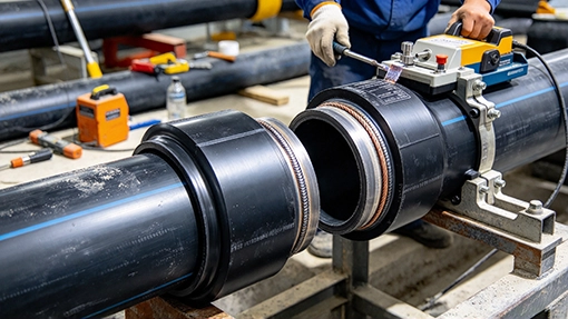
PE gas pipe fusion joint
What to Ask Before the Test Plan
The technical detail above only becomes procurement value when it turns into questions a buyer can actually ask. Five items belong on the pre-test checklist.
① Which standard governs the test parameters, and does the supplier’s documentation align with it?
Confirm whether the project is operating under GB/T 51455-2023 / CJJ 63-2018, EN 1555 with a national annex, or ASTM D2513 / F2620 practice. The test pressure multiples and hold durations are not identical across systems. A supplier who quotes a single “standard” test pressure without asking which code applies is not giving you an engineering answer.
② Does the SDR and pressure class of the supplied pipe match the design pressure used to calculate the test pressure?
The 0.4 MPa strength-test floor applies to SDR11 PE100 in the GB framework. SDR17 pipe sits at a 0.2 MPa floor. If the pipe class and the test pressure calculation were done by different people without cross-checking, the test plan can specify a pressure the pipe is not rated to see.
③ Can the supplier provide fusion parameter records and joint traceability?
The site test verifies the system, but if a joint fails the strength test, the conversation shifts to why. Fusion pressure, heater temperature, heating time, and cooling time records are what separate a systematic quality problem from a one-off field error. Traceability back to the jointing crew and the fusion machine record is the difference between corrective action and guesswork.
④ Has the test medium been agreed, and is the dewatering/drying procedure defined if water is used?
For PE gas lines, the water vs. air decision is not a preference. It has consequences for commissioning schedule, moisture specification compliance, and site safety. Get the medium written into the test plan, and get the post-hydrostatic drying procedure written next to it.
⑤ Does the test plan include hourly logging, or only start/end readings?
A 24-hour tightness test with only two data points is not a test record; it is a snapshot. The hourly log—and the temperature and barometric data that feed the corrected pressure drop calculation—is what makes the result defensible if the line is questioned later.
FAQ: Buyer Questions
Q1: What is the difference between a strength test and a tightness test on PE gas pipe?
A strength test proves the installed system can withstand a pressure above operating level without structural failure. A tightness test proves it does not leak at a pressure closer to operating level. They use different test pressures, different hold durations, and different pass criteria. Passing one does not substitute for the other.
Q2: What pressure should a PE gas pipe be tested at?
Under the GB/T 51455-2023 / CJJ 63-2018 framework, the PE SDR11 strength test is 1.5× design pressure with a 0.4 MPa minimum; SDR17 uses a 0.2 MPa minimum. The tightness test is generally 1.1× design pressure (some project specifications use 1.15×), with a 0.1 MPa minimum for medium-pressure and above. EN 1555 and ASTM D2513 projects follow their own national annexes and project specifications—confirm the governing code before fixing the test pressure.
Q3: How long does a PE gas pipe tightness test take?
For buried PE gas piping under the GB framework, the tightness test hold duration is 24 hours, with readings recorded at least once per hour. The pass criterion is a corrected pressure drop below 133 Pa, not a raw gauge reading comparison.
Q4: Can PE gas pipe be pressure tested with air?
Compressed air is commonly used for tightness testing in PE gas piping, and CJJ 63-2018 lists compressed air as the preferred tightness test medium. But pneumatic testing stores far more energy than hydrostatic testing at the same pressure. If air is used for a strength test or a large-volume tightness test, the test plan needs a hazard assessment, defined exclusion zones, and a controlled pressure ramp. “Can be done” and “can be done safely” are two different questions.
Q5: Does a factory hydrostatic test replace site pressure testing?
No. The factory test verifies material-level hydrostatic strength—typically 20°C, 100 h, 12.0 MPa hoop stress for PE100. The site test verifies the installed system, including fusion joints, fittings, and connections that did not exist at the factory. A pipe can pass the factory test and still produce a leaking system if the jointing was defective.
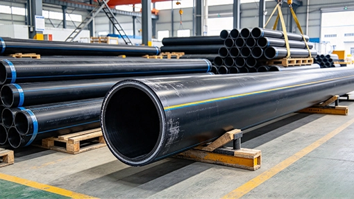
PE Gas Pipe
The Last Check Before Backfill
A PE gas pipe pressure test does not make a system safe. It reveals whether the system that was built is the system that was designed. The 1.5× / 1.1× pressure split exists because structural failure and leakage are different failure modes. The 133 Pa corrected pressure drop threshold exists because a 24-hour test in a trench is a thermodynamic measurement as much as a leak measurement. And the water vs. air decision exists because the consequences of getting it wrong are not symmetric.
If you are sourcing PE gas pipe for a project where the test plan has to hold up to scrutiny—not just pass a site inspection—send us the design pressure, SDR, applicable code, and test medium requirements. Luoyang Datang Energy Tech Co., Ltd. will respond with the pipe specification, fusion parameter documentation, and the traceability records that let your test plan stand on evidence.