LUOYANG DATANG ENERGY TECH CO.,LTD


How Much Weight Can a Pipe Clamp Hold? Understanding Load Capacity and Support Conditions
Two pipe clamps of the same nominal size can carry very different loads. One might be rated for a few hundred pounds; another, built with a heavier body and additional bolts, can handle several thousand. The pipe diameter tells you what the clamp fits around — it does not tell you what the clamp can safely hold.
A pipe clamp’s load capacity depends on its material and size, but also on its design, fasteners, mounting structure, and the conditions of installation. This article explains what actually drives the number on the datasheet, and how to use that number without overestimating the support system around it.
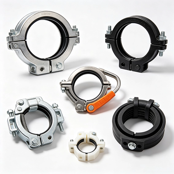
industrial pipe clamps with different structures
1. What Determines Pipe Clamp Load Capacity?
Five factors decide how much a clamp can carry. None of them works alone.
Clamp material
Carbon steel is the baseline for general industrial piping, with predictable strength and cost. Stainless steel (304 or 316) brings corrosion resistance for washdown, marine, or chemical environments, but the allowable stress can differ from carbon steel at elevated temperatures. Galvanized steel adds a zinc coating for outdoor exposure — the coating helps corrosion resistance, not structural capacity.
Clamp design and structure
A U-bolt relies on two threaded legs and the stiffness of the pipe-to-support contact. A two-bolt clamp spreads the load across a split body. A three-bolt heavy-duty clamp adds a third bolt and a heavier section, which changes how the clamp resists bending and transverse loads. Cushioned clamps introduce an elastomer liner — useful for vibration, but the liner hardness and construction also influence how the assembly behaves under load.
Pipe diameter and clamp fit
Larger pipe sizes generally pair with larger, heavier clamp bodies, but the relationship is not linear. A clamp that is loose on the pipe, or that contacts the pipe over a narrow band, concentrates stress and reduces the effective capacity of the connection.
Fasteners and connections
The clamp body is only one link. Bolt grade and diameter, nut engagement, and thread condition set the ceiling for how much clamping force the joint can sustain. A high-capacity clamp body bolted with undersized or low-grade fasteners does not deliver its rated capacity.
Mounting structure
The clamp transfers load into whatever it is bolted to: a Unistrut channel, a structural beam, a wall bracket, or a hanger rod. If the channel strut, anchor, or rod is the weakest element, the clamp’s rating is irrelevant. The support structure sets the real limit.
Table 1. What each factor controls
| Factor | Effect on load capacity |
|---|---|
| Material | Strength and allowable stress at operating temperature |
| Clamp design | Load path, bending resistance, number of bolts |
| Pipe size and fit | Contact area and stress distribution |
| Fasteners | Joint strength and clamping force |
| Mounting structure | The actual ceiling of the support system |
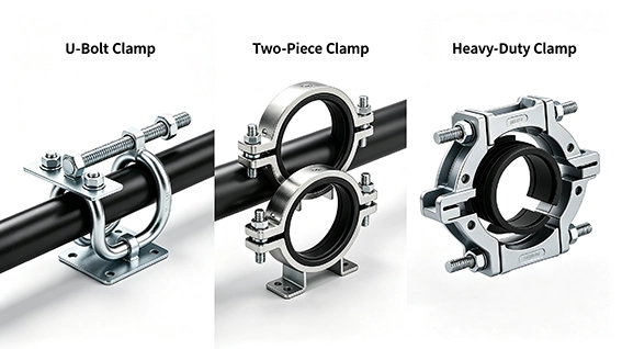
different pipe clamp designs
2. Do Different Types of Pipe Clamps Have Different Load Ratings?
Yes — but the type label is a starting point, not the answer. The same “pipe clamp” category covers products with very different structural behavior.
U-bolt clamps are common for light to medium horizontal pipe runs on beams or channel. Their capacity depends heavily on bolt strength and how the U-bolt seats against the support. Representative carbon steel values per MSS SP-58 put an NPS 2 U-bolt at roughly 5 kN (1,125 lbf) and an NPS 4 U-bolt at roughly 8 kN (1,800 lbf) .
Two-bolt clamps add a split body and a second fastener. At NPS 2, the representative maximum load is around 8 kN (1,800 lbf) ; at NPS 4, about 14 kN (3,150 lbf) .
Three-bolt heavy-duty clamps are built for higher loads, larger pipe, or dynamic service. At NPS 4, a representative rating is approximately 22 kN (4,950 lbf) ; at NPS 8, around 36 kN (8,100 lbf) .
Clevis hangers behave differently because they suspend the pipe from a rod. A light-duty clevis for 1/2-inch pipe may be rated around 610 lbs with a 3/8-inch rod; a 6-inch clevis can reach roughly 1,940 lbs with a 3/4-inch rod. The rod, not the clamp body, often becomes the limiting component.
Cushioned clamps trade some raw load path for vibration isolation. Their capacity depends on the insert material, the clamp body, and the bolt arrangement — the elastomer should not be treated as a free upgrade to load rating.
The rule that survives all type comparisons: do not infer capacity from the product category. Use the manufacturer’s published load rating for the exact model and size, and confirm the test conditions behind it.
3. How Does Pipe Weight Affect the Required Clamp Capacity?
The clamp does not carry “the pipe.” It carries the pipe, everything inside it, everything wrapped around it, and the hardware attached to it — distributed according to the support layout.
The load components to account for include:
- Pipe self-weight — the empty pipe, based on outside diameter, wall thickness, and density.
- Fluid or gas content — water-filled lines are substantially heavier than empty lines; gas lines are lighter but not weightless.
- Insulation and cladding — thermal or acoustic insulation adds dead load and may increase the clamp’s effective diameter.
- Fittings and valves — flanges, valves, strainers, and in-line instruments are concentrated loads that may need their own support.
- Dynamic and operational loads — vibration, water hammer, thermal expansion, and seismic design actions.
The critical mistake is dividing total weight evenly by the number of clamps. Load distribution depends on span, support stiffness, elevation, and where the concentrated loads sit. A valve near mid-span does not share its weight equally with a clamp two meters away.
Table 2. Load components that reach the clamp
| Load component | What to include |
|---|---|
| Pipe weight | Empty pipe per unit length |
| Contents | Liquid or gas, based on operating condition |
| Insulation | Thermal/acoustic material and cladding |
| Fittings and valves | Concentrated loads, often needing separate support |
| Dynamic loads | Vibration, expansion, seismic, water hammer |
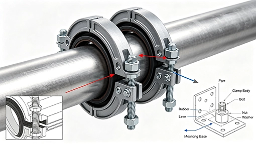
pipe clamp fasteners and mounting connections
4. Why Does Pipe Support Spacing Matter?
Support spacing changes the load each clamp sees. Shorten the span, and the load per support drops; lengthen it, and both the clamp load and pipe deflection rise.
There is no universal spacing table that fits every project. Spacing depends on pipe material, diameter, wall thickness, operating temperature, fluid content, and the governing design code. For reference, a typical specification following ANSI B31.1 practice lists maximum support spacing of about 7 ft for 1-inch-and-smaller steel pipe, 10 ft for 2-inch pipe, 14 ft for 4- and 5-inch pipe, and 17 ft for 6-inch-and-larger pipe in liquid service — with rod diameters increasing from 3/8 inch to 1-1/8 inch across that range.
Those numbers are illustrative, not a substitute for project engineering. Two additional points matter more than any single spacing value:
Concentrated loads need their own support. A valve, flange pair, or heavy fitting between standard supports can overload the nearest clamp even if the spacing looks correct on the general arrangement.
Deflection is a separate check. ASME B31.1 and B31.9 set different deflection limits for power piping and building services piping. A spacing that satisfies stress limits may still allow visible sag or interfere with drainage slope.
5. How to Check the Load Rating of a Pipe Clamp?
A load rating is only meaningful when you know what it covers. Work through four steps before accepting a published number.
Step 1 — Identify the exact model and size. A “2-inch pipe clamp” is not a specification. The model number, body material, bolt count, and liner configuration all change the rating.
Step 2 — Read the manufacturer’s rating and the test conditions. Load direction matters: a clamp rated for vertical download may have a much lower transverse or longitudinal capacity. Some catalogs publish a safety factor of 3 on the design load; others use 5 on the ultimate load. A rating without its basis is not comparable to another rating.
Step 3 — Verify the fasteners and the structure. Check bolt grade and diameter, rod size, channel strut capacity, and anchor pull-out. The clamp cannot transfer more load than the connection below it can accept.
Step 4 — Confirm the complete assembly. The allowable load is set by the weakest link in the load path — clamp, bolt, rod, channel, anchor, or bracket — evaluated against the governing code and the required safety factor. MSS SP-58 establishes minimum design load ratings for pipe hanger assemblies precisely because the assembly, not the clamp alone, is the rated unit.
Table 3. Load rating verification checklist
| Item | What to confirm |
|---|---|
| Clamp model | Body type, size, material, liner |
| Rated load | Published value and load direction |
| Test basis | Safety factor, test method, temperature basis |
| Fasteners | Bolt grade, diameter, engagement |
| Support structure | Channel, rod, anchor, or bracket capacity |
| Governing standard | MSS SP-58, project specification, or code requirement |
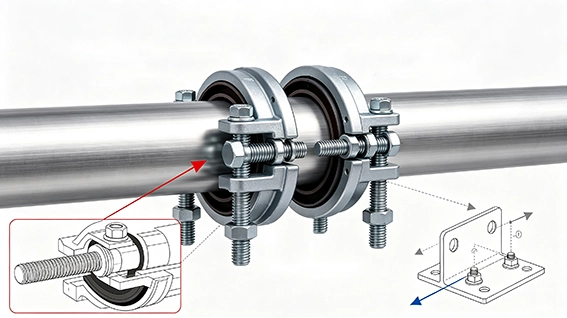
a Load-Bearing Pipe Clamp
6. What Should Buyers Consider When Selecting a Load-Bearing Pipe Clamp?
A clamp that works on the drawing can still fail at the project if the purchase specification misses the conditions around it. Bring these items to the quotation request:
- Pipe outside diameter — not just nominal size; OD is what the clamp actually grips.
- Pipe material and operating temperature — stainless, carbon steel, and elevated temperature change the allowable stress basis.
- Total supported load per clamp — calculated from pipe, contents, insulation, and concentrated loads, not estimated from a generic table.
- Installation orientation — horizontal, vertical, ceiling-suspended, or wall-mounted; each changes the load path.
- Clamp material and surface treatment — carbon steel, stainless steel, galvanized; indoor or outdoor exposure.
- Vibration and expansion requirements — cushioned or rigid, guided or restrained.
- Manufacturer’s load rating and documentation — the rated value, test basis, and standard compliance.
- Quantity and delivery schedule — project sequence often determines whether a standard model or a custom configuration is practical.
Table 4. What to provide when requesting a quote
| Project requirement | Information to supply |
|---|---|
| Pipe size | Outside diameter and wall thickness |
| Pipe material | Carbon steel, stainless steel, other |
| Operating conditions | Temperature, fluid, indoor/outdoor |
| Installation | Wall, ceiling, channel, or hanger rod |
| Design load per support | Calculated load, including safety factor |
| Quantity | Project quantity and required delivery |
FAQ
Q1: What is the maximum load of a pipe clamp?
There is no single maximum. Representative carbon steel values per MSS SP-58 range from roughly 5 kN (1,125 lbf) for an NPS 2 U-bolt to about 75 kN (16,875 lbf) for an NPS 24 three-bolt clamp. The applicable value depends on clamp type, size, material, bolt configuration, and the manufacturer’s test basis. Always use the published rating for the exact model.
Q2: Does a larger pipe clamp always have a higher load rating?
Not necessarily. A larger clamp body may pair with small bolts or a light mounting bracket. The rating follows the weakest component in the load path — clamp, fastener, rod, channel, or anchor. A large clamp on an undersized channel strut is limited by the channel, not the clamp.
Q3: What safety factor is used for pipe clamp load ratings?
It varies by product and standard. Some clamp manufacturers publish ratings with a safety factor of 3 on the design load; others use 5 on the ultimate load. MSS SP-58 establishes minimum design load ratings but does not impose a single universal safety factor across every product category. The safety factor must be read together with the test method and the governing project specification.
Q4: Can I use the clamp’s load rating as the capacity of the whole support?
No. The clamp rating covers the clamp body under specified test conditions. The pipe support system includes the clamp, bolts, hanger rod or channel, anchors, and the structure behind them. The allowable load of the system is governed by the weakest element and the applicable design code — not by the clamp catalog number alone.
Need Pipe Clamps for an Industrial Piping Project?
If the load calculation is complete but the clamp selection is not, send us the pipe OD, material, operating temperature, support arrangement, and design load per support. We can match the clamp body, bolt configuration, material, and surface treatment to the actual support condition — not just the nominal pipe size.
Available options include: carbon steel and stainless steel clamp bodies; U-bolt, two-bolt, three-bolt, and heavy-duty configurations; galvanized and other surface treatments; cushioned and rigid designs; and project-specific dimensional or load requirements.
Share your pipe schedule and support layout. Luoyang Datang Energy Tech Co., Ltd. will come back with a clamp specification that fits the assembly, not one that looks right only on the line list.
RELATED POSTS
Structural Transformation of the Global Pipe Industry: Regional Differentiation and Technological Upgrading Opportunities under Slowing Growth
What Type Of Water Pipe Can Be Used When Attached To A Municipal Water Supply
PVC Pipe vs. HDPE Pipe: Which is better?
Brass Pipe Fittings Sizes Explained: Threads, Dimensions and Selection Guide